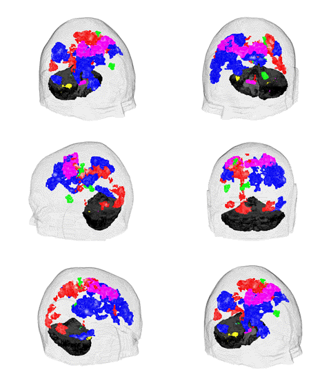
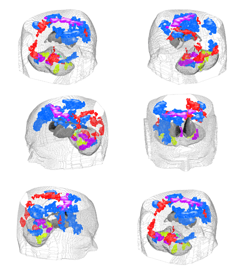
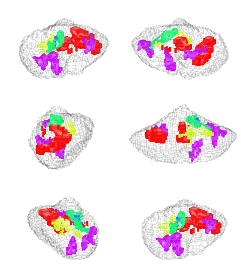
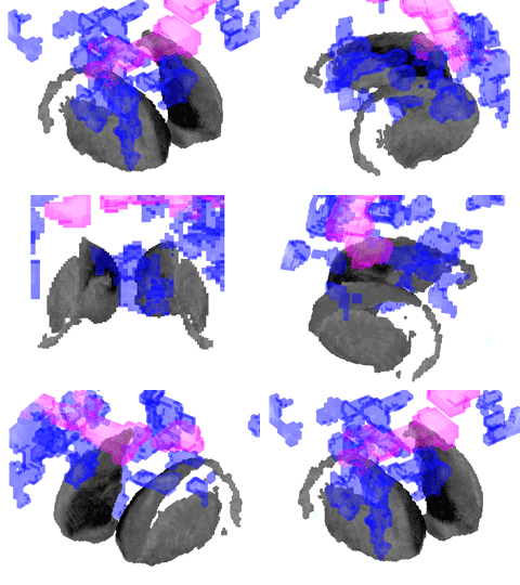
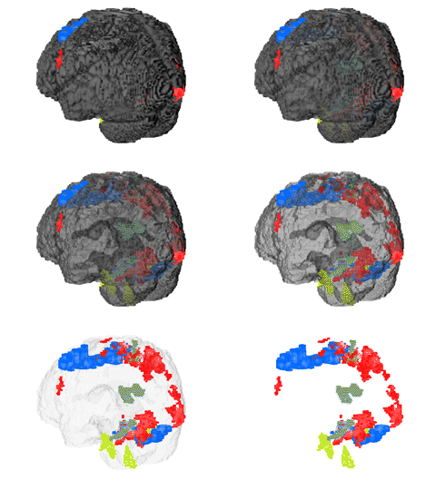
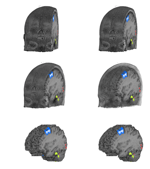
5. '3D Visualization' panel
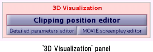
このプログラムは、複雑に重なり合うContrastデータを3次元表示することができます。'3D Visualization'
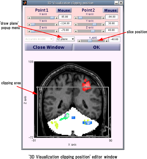
panelの'Clipping position editor' buttonをクリックすると表われる '3D Visualization clipping
position' editor windowで、Contrastデータを3次元表示するclipping領域を指定します。ここで 'Select files' panelで、ROIファ
イルを指定していた場合、ROIファイルに記述している脳構造物を3次元表示します。また、'Detailed
parameters (Draw)' editor windowの 'Background mode' popup menuで
'edge' または 'image&edge'
を選択している場合、Structure画像から検出したedgeも3次元表現の対象とします。
また、3次元画像の動画ファイル(MPEG1
format)を作成することができます。動画ファイルの作成は3次元表示をしている状況で、'MOVIE screenplay
editor' buttonをクリックすると表われる 'MOVIE
screenplay' editor windowでおこないます。
5.1. '3D Visualization
clipping position' editor window
'3D Visualization' panelの
'Clipping position editor' buttonをクリックすると '3D Visualization clipping
position' editor windowが表われます。'3D Visualization clipping position'
editor windowで、3次元表示するclipping領域を指定します。
3次元表示するclipping領域は
、Point1とPoint2の2点で囲まれた矩形領域で指定します。Point1とPoint2は、各座標軸のsliderと数値boxで指定してくだ
さい。また 'Mouse' buttonをクリックした後、'3D Visualization clipping position'
editor windowの下段の画像の上をクリックすれば、クリックした座標をclipping positionに設定します。'3D
Visualization clipping position' editor
window中段のGUIで、slice画像を表示する平面とslice座標を指定します。指定したslice座標がclipping矩形領域内なら、
slice画像の上にclipping位置を矩形表示します。
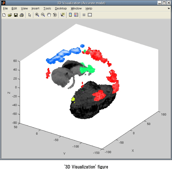
'3D Visualization clipping position'editor windowの 'OK' buttonをクリックすると
'3D Visualization' figureが表われます。'3D Visualization'
figureには、clipping領域内のContrastデータとROIファイルの脳構造物を3次元表示します。
5.2.
'Detailed parameters (3D Visualization)' editor window
'3D Visualization' panelの
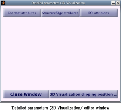
'Detailed parameters editor' buttonをクリックすると 'Detailed parameters (3D
Visualization)' editor windowが表われます。'Detailed parameters (3D
Visualization)' editor windowで、3次元表示データの表示属性を設定します。
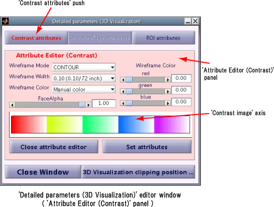
'Detailed parameters (3D Visualization)' editor window上段の'Contrast
attributes' button, 'StructureEdge attributes' button, 'ROI attributes'
buttonをクリックすると、それぞれのbuttonに対応するAttribute editorが表われます。
5.2.1. 'Attribute
Editor (Contrast)' panel
'Detailed
parameters (3D Visualization)' editor windowの 'Contrast
attributes' buttonをクリックすると、'Attribute Editor (Contrast)'
panelを表示します。'Attribute Editor (Contrast)'
panelでは、Contrastデータの表示属性を設定します。
MATLAB R14 Service Pack 2 (Version 7.0.4)以上のversionのMATLABでは、'Attribute
Editor (Contrast)' panelの下部に、'Contrast image' axisを表示します。'Contrast
image' axisには、'Attribute Editor (Contrast)'
panelで編集中の表示属性でのContrastデータのイメージ画像を表示します。
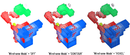
・ 'Wireframe Mode', 'Wireframe Width', 'Wireframe Color'
'Wireframe Mode' popup menuでContrastデータのwireframe表示モードを指定します。
'OFF' の場合Contrastデータのwireframeは表示しません。'CONTOUR'
の場合はContrastデータ外周のみwireframeを表示し、'VOXEL'
を選択した場合はContrastデータの全てのvoxelに対するwireframeを表示します。
'Wireframe Width' popup menuと 'Wireframe Color' popup
menuで、wireframeの太さと色を指定します。( 'Wireframe Width' popup menuと 'Wireframe
Color' popup menuは 'Wireframe Mode' popup menuで 'OFF' 以外を選択している時のみ設定可)
'Wireframe Color' popup menuで 'Contrast color'
を選択すると、Contrastデータの色でwireframeを表示します。'Manual color' を選択した場合は、'Attribute
Editor (Contrast)' panelの右側のGUIでwireframeを表示する色を指定します。
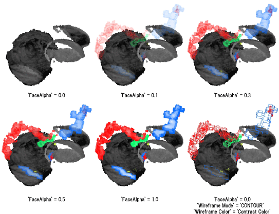
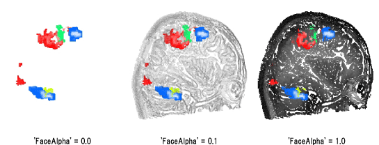
・ 'FaceAlpha'
'FaceAlpha' のsliderと数値boxで、Contrastデータの面の透明度を指定します。
'FaceAlpha'
が1.0ならContrastデータの面は不透明となり、Contrastデータの内部や裏側に隠れている構造物等は見えませんが、
'FaceAlpha' に0.0を設定すると、Contrastデータの面は透明となり、Contrastデータの内部や後ろの構造物が表われます。
5.2.2.
'Attribute Editor (Structure Edge)' panel
'Detailed
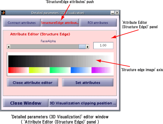
parameters (3D Visualization)' editor windowの 'StructureEdge
attributes' buttonをクリックすると、'Attribute Editor (Structure Edge)'
panelを表示します。'Attribute Editor (Structure Edge)'
panelでは、Structure画像のedgeの表示属性を設定します。
MATLAB R14 Service Pack 2 (Version 7.0.4)以上のversionのMATLABでは、'Attribute
Editor (Contrast)' panelの下部に、'Structure edge image'
axisを表示します。'Structure edge image' axisには、'Attribute Editor (Structure
Edge)' panelで編集中の表示属性でのStructure画像のedgeのイメージ画像を表示します。
・ 'FaceAlpha'
'FaceAlpha' のsliderと数値boxで、Structure画像のedgeの面の透明度を指定します。
'FaceAlpha'
が1.0ならStructure画像のedgeの面は不透明となり、Structure画像のedgeの内部や裏側に隠れている構造物等は見えませんが、
'FaceAlpha'
に0.0を設定すると、Structure画像のedgeの面は透明となり、Structure画像のedgeの内部や後ろの構造物が表われます。
5.2.3. 'Attribute Editor
(ROI)' panel
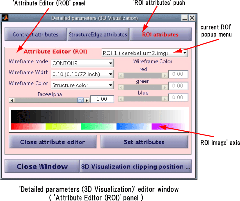
'Detailed parameters (3D
Visualization)' editor windowの 'ROI attributes'
buttonをクリックすると、'Attribute Editor (ROI)' panelを表示します。'Attribute Editor
(ROI)' panelでは、ROIデータの表示属性を設定します。
MATLAB R14 Service Pack 2 (Version 7.0.4)以上のversionのMATLABでは、'Attribute
Editor (ROI)' panelの下部に、'ROI image' axisを表示します。'ROI image'
axisには、'Attribute Editor (ROI)' panelで編集中の表示属性でのROIデータのイメージ画像を表示します。
・ 'current ROI' popup menu
表示属性を設定するROIデータを選択します。(以下 'current ROI' popup menuで選択しているROIデータをcurrent
ROIと呼ぶ)
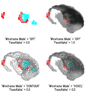
・ 'Wireframe Mode', 'Wireframe Width', 'Wireframe Color'
'Wireframe Mode' popup menuでcurrent ROIデータのwireframe表示モードを指定します。
'OFF' の場合current ROIデータのwireframeは表示しません。'CONTOUR'の場合はcurrent
ROIデータの外周のみwireframeを表示し、'VOXEL' を選択した場合はcurrent
ROIデータの全てのvoxelに対するwireframeを表示します。
'Wireframe Width' popup menuと 'Wireframe Color' popup
menuで、wireframeの太さと色を指定します。( 'Wireframe Width' popup menuと 'Wireframe
Color' popup menuは 'Wireframe Mode' popup menuで 'OFF' 以外を選択している時のみ設定可)
'Wireframe Color' popup menuで 'Contrast color'
を選択すると、ROIデータの色でwireframeを表示します。'Manual color' を選択した場合は、'Attribute
Editor (ROI)' panelの右側のGUIでwireframeを表示する色を指定します。
・ 'FaceAlpha'
'FaceAlpha' のsliderと数値boxで、current ROIデータの面の透明度を指定します。
'FaceAlpha' が1.0ならcurrent
ROIデータの面は不透明となり、ROIデータの内部や裏側に隠れている構造物等は見えませんが、'FaceAlpha'
に0.0を設定すると、current ROIデータの面は透明となり、ROIデータの内部や後ろの構造物が表われます。
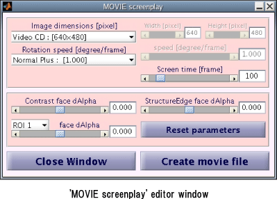
5.3. 'MOVIE
screenplay' editor window
'3D Visualization' panelの 'MOVIE
screenplay editor' buttonをクリックすると 'MOVIE screenplay' editor
windowが表われます。
'MOVIE screenplay' editor windowで、3次元表示画像の動画ファイル(MPEG1
format)を作成します。
・ 'Image dimensions'
'Image dimensions' popup menuで動画の画像サイズを指定します。'Image dimensions' popup
menuで 'manual mode' を選択した場合は、'Image dimensions' popup
menuの右側のSliderと数値boxで画像サイズを指定します。
・ 'Rotation speed', 'Screen time'
動画ファイルは、Camera targetを中心にZ軸にそって視点位置を回転させた時の画像から作成します。'Rotation speed'
popup menuで視点を回転させる速度を指定します。'Rotation speed' popup
menuで正の値を選択した場合、視点はZ軸に沿って反時計回りに回転し、負の値なら時計回りに回転します。'Rotation speed'
popup menuで 'manual mode' を選択した場合は、'Rotation speed' popup
menuの右側のSliderと数値boxで視点の回転速度を指定します。また、'Screen time'
popup menuで動画のframe数を指定します。
・ 'face dAlha'
'Contrast face dAlpha', 'StructureEdge face dAlpha', 'ROI face dAlpha'
で、Contrastデータ、Structure画像のedge部分、ROIデータの面の、1フレーム毎の透明度の変位を指定します。動画開始時は'3D
visualization' figureの透明度から開始し、1フレーム毎に、ここで指定した値で透明度を変化されてゆきます。
・ 'Create movie file' button
動画ファイルを作成する為のパラメータを設定後、'Create movie file' buttonをクリックしてください。'Select
file' windowが表われます。ここで作成する動画ファイル名を指定してください。
[注意]
動画ファイルの作成は非常に不安定です。作者の環境では、動画ファイルを生
成した直後にMATLABがハングアップしてしまいます。ま
たこの処理は大量のメモリを消費します。メモリ容量が小さい計算機ではご
注意ください。
・Gallery


